|
|
||
|
|
||
|
|
||
|
INHALTSVERZEICHNIS_____________________________________________IHM
SD
Introduction
...........................................................................................................................
2
Drive 4 WD
.........................................................................................................................
4
Transmission
.................................................................................................................................
5
Hanging up
.......................................................................................................................
6
Brakes
................................................................................................................................
8
Power steering
.........................................................................................................................
9
Räderund vehicle drive (general
references)
.........................................................................
10
Drive system Viscomatic clutch
...........................................................................
11
Hydraulic control circuit
............................................................................................................
17
Electronic Kontrollanlage
.................................................................................................
22
Funktionsiogik of the system
..................................................................................................
25
Components of the system
....................................................................................................
35
Diagnostics of the system
........................................................................................................
42
Abs system, version for four
drive wheels
................................................................... 43
General description
......................................................................................................
44
Interference logic for the
version 4 WD
........................................................................................
45
Localization components of the
system
.............................................................................
48
Description of function
..........................................................................................................
52
Selbstdiagnose
......................................................................................................................
53
Electronic engine management
Motronic M 3,7 ........................................................
54
MotronicM3.7
.......................................................................................................................
58
Operation diagramme
...................................................................................................................
62
Electronic steering box
..............................................................................................
64
Components
........................................................................................................................
65
Selbstdiagnose
......................................................................................................................
69
Fuel system circle
...................................................................................................
70
On-board board
..............................................................................................................................
74
Notes/notes
...........................................................................................................
77 |
||
|
|
||
|
|
||
|
1Bi§
B_________________________________________________EINLEITUNG
Introduction
The available publication
documents the variants and the systems, which were specifically developed
for the 1B^S. They are to be described here and in the detail represented,
thus all necessary information for the general knowledge of the vehicle
and the operational principle of the different plants, systems and above
all the electronic controls be conveyed can. |
||
|
|
||
|
2 |
||
|
|
||
|
|
||||
|
MECHANICAL
GROUPS |
||||
|
|
||||
 |
 |
 |
||
|
|
||||
|
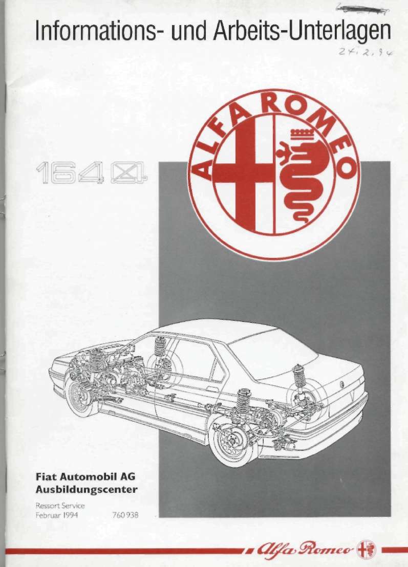
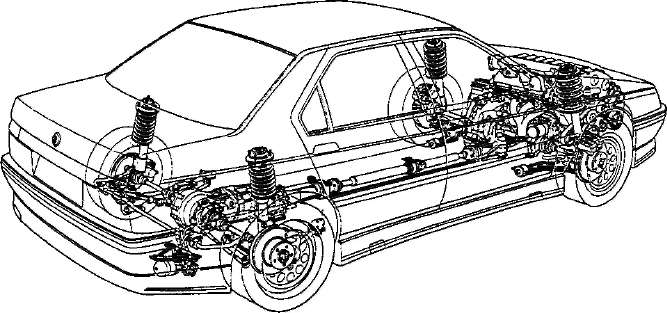
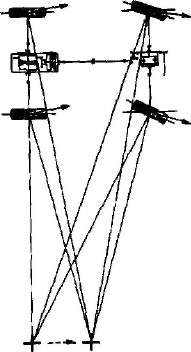
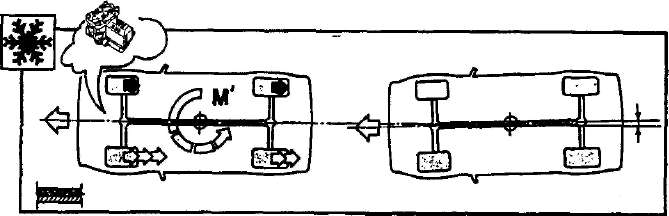
The
all-wheel drive system Viscomatic, which finds with the new ISA BÖL
use, was developed exclusively by the Alfa Rome EO technical
designers in co-operation with Steyr Puch.
With 164
was still continued to improve the characteristics of the all-wheel drive
owing to „the active " drive system,
in which the moment distribution varriert continuously according to the given
logics, depending upon driving
condition (drive torque, guidance angle, driving speed, process between
front axle and rear axle), which are calculated by the electronic steering box VISCOMATIC®.
One
received so an all-wheel drive, which gives new 164 high „driving safety " in
each driving condition and in the most
diverse situations. |
||||
|
|
||||
 |
||||
|
|
||||
|
The reached advantages can be
summarized in such a way:
- To limit „active " interference of the system,
which administers the torque
process variable, but continuously, without the travelling
comfort;
- maximum stability when braking, by a
special version of the ABS for 4WD;
- no influence of the drive with driving
along curves, due to the construction;
- high achievements of the entire system, due
to the good quality of the construction;
- A construction, which made possible it
to accomplish an adjustment without
large changes at the past model 164 with 2 drive
wheels. |
||||
|
|
||||
 |
||||
|
|
||||
|
|
|||
|
|
MECHANICAL GROUPS |
||
|
|
|||
|
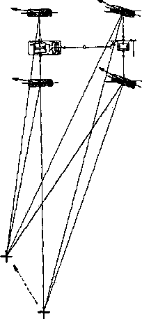
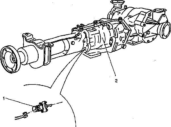
4WD
propelled
The unpublished construction
solution of the drive for *$sk£k the Sl plans a mechanical
TRANSMISSION with 6 COURSES. The allocation of the drive over a
VISCOMATIC^ clutch with ELECTRONIC CONTROL, as well as a Torsen
Diffe
“rential
an~cJer Hinteractrse.
- |
|||
|
|
|||
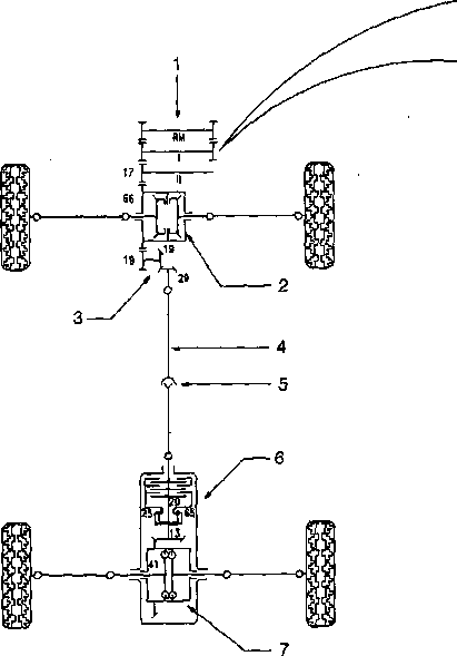 |
1. Course: 3.769
2. Course: 2.333
3. Course: 1.680
4. Course: 1.290
5. Course: 1.031
6. Course: 0,837 R. Gang: 3.720 |
||
|
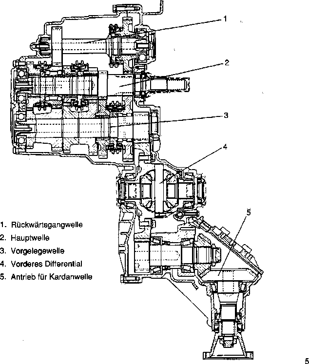
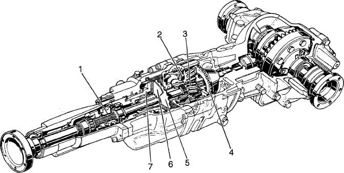
1.
Transmission
2. Front differential
3. Reduction gear
4.
Drive shaft
5. Universal joint
6. Clutch VISCOMATIC®
7. Rear differential
Torsen |
|||
|
|
|||
|
(The numbers indicate the number of teeth of the different
wheel transmissions) |
|||
|
|
|||
|
The
kinematic pattern plans a VISCOMATIC® clutch between the front axle
and the rear axle. The torque between the two wheels is subdivided in
front by a conventional differential, while on the rear axle a gate EN
differential was used, so that the drive in each situation is
maximally used.
Owing
to the special construction of the Torsen it makes this kind
of self-locking that for differential possible, with small adhesion of a Rades,
the drive moment on the wheel with the better road grip too transferred (up to the
quadruple value). |
|||
|
|
|||
|
|
|||
|
MECHANICAL
GROUPS |
.16 |
||
|
|
|||
|
Transmission
With (
 a new transmission of the company GET-RISE
UP with 6 courses begun, that a new transmission of the company GET-RISE
UP with 6 courses begun, thataccordingly one
designed, in order to make possible fast accelerations, due to the appropriate gradations of the courses. In
this way the maximum torque of the engine (which is very high)
is, always at all wheels and
in each operating condition available. This results in an unexpected
acceleration behavior for a vehicle of this kind with constructional equipment opposite a
2-Radantrieb. |
|||
|
|
|||
|
The
transmission range contains also the front differential and the drive for
the cardan shaft. |
|||
|
|
|||
 |
|||
|
|
|||
 |
|||
|
|
|||
|
|
||
 |
||
|
|
||
|
Hanging up
The
hanging up were again designed, extensive and complex experiments to keep
accomplished around a maximum
handling and comfort for this 4WD-Fahrzeug. This vote was reached
together with the optimization of the specific operating logics of the
VISCOMATIC clutch, which are
connected in special way with the behavior of the hanging up. |
||
|
|
||
|
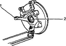
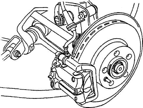
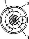
Front suspension
The front
suspension became within the range of the position of the steering arm (1)
on the hub (2) changed. |
||
|
|
||
 |
||
|
|
||
|
In addition all points of the
suspension became to the specific sportiven characteristics
the vehicle adapted, thus
high guidance precision was reached.
The
feathers/springs and shock absorber have a special characteristic. In the
shock absorbers are additional
feathers/springs, which intervenes in the delimitation phase as an
anti-centrifuge and an anti-pitch oscillation function. This makes
one possible „softer " measuring of the external feathers/springs for the increase of
the travelling comfort. |
||
|
|
||
 |
||
|
|
||
|
The
applied solutions make possible to
adapt the high achievements to the sensitivity of the steering
element, with from-following
stability in curves, even if border situations
are
reached. |
||
|
|
||
|
|
||||
|
MECHANICAL GROUPS |
M |
|||
|
|
||||
|
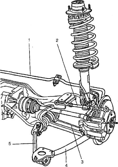
Rear suspension
It was completely again
designed, in order to ensure the demands of the new drive
system.
The new suspension is
characterized by the following:
- A lower wishbone (3), which
takes up the lateral load;
- An upper unreactive
(2);
- A lever (4) and a linkage (5)
in longitudinal direction;
- A stabilizer (1), for the
entire reconciliation of the group.
The elasticity of the system
under transverse loads makes an easy self-steering possible with
stabilizing effect. |
||||
|
|
||||
|
1. Stabilizer
2. Upper unreactive
3. Lower Schwingarm
4. Semi-trailing arm
5. Linkage |
 |
|||
|
|
||||
|
7 |
||||
|
|
||||
 |
 |
|||
|
|
||||
|
|
|||
 |
MECHANICAL
GROUPS |
||
|
|
|||
|
Also at
the rear suspension feathers/springs and shock absorbers have specific
measuring and the shock absorbers to
have an internal feather/spring, like the front.
The
applied solutions make as a further improving, and an optimal power transmission at the
rear axle in the course for the steering control possible as also in the thrust.
Hanging up with controlled absorption
The
electronic Kontroilsystem SCS varied in the measuring of the shock
absorbers and is the same system,
which already worked with the other versions 164. The interference logic was adapted to the new
drive system. |
|||
|
|
|||
|
Brakes
The
brake assembly was again developed accordingly for this vehicle and equipped with a specific power steering and ventilated
brake disks.
Due to
the high demanded achievements the brake pliers were again developed, in
order to thus achieve a higher
efficiency. |
|||
|
|
|||
 |
|||
|
|
|||
|
|
|||
|
MECHANICAL
GROUPS |
% |
||
|
|
|||
|
Power steering
The
plant of the power steering was adapted to the specific characteristics of
this vehicle. The hydraulic guidance pump - propelled by the Poly V belt
of the crankshaft - consists of two
separated pumps - power steering and Viscomatic -. Both pumps are attached at the same supply cycle. The
steering housing is specific, since in this the guidance sensor is, which belongs to
the VISCOMATIC system. |
|||
|
|
|||
 |
|||
|
|
|||
|
1. Hydraulic guidance pump
2. Header tank |
|||
|
|
|||
|
3.
Zulaufleitungen
4.
Steering housing
5.
Return pipes
6. Inlet and return pipes VISCOMATIC
plant |
|||
|
|
|||
 |
|||
|
|
|||
|
|
||
|
1B£1
El_________________________________MECHANISCHE GROUPS
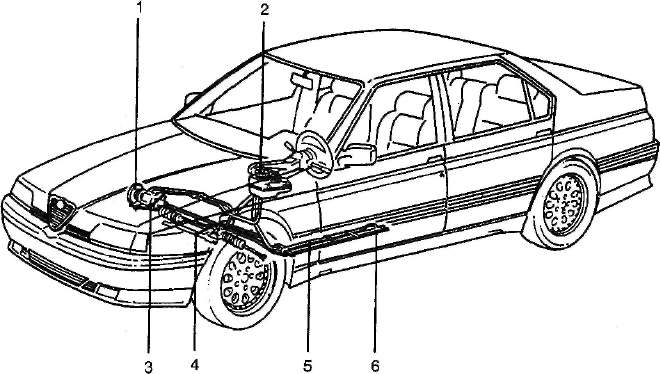
Wheels and vehicle
drive
With
vehicles with all-wheel drive, the automatic work on the wheels and the
vehicle towing are problematic, since the two axles must be
separated before.
With
 is
the VISCOMATIC system with an appropriate mechanical is
the VISCOMATIC system with an appropriate mechanicalSystem
equipped that complete switching off makes possible for the VISCOMATIC
clutch. According to turning the engine (ignition off out) after
approximately 4 min. the connection to
the rear axle is separated automatically.
Only
after this time interval is:
- balancing the individual wheels at the
vehicle
- towing the vehicle
possible. |
||
|
|
||
|
10 |
||
|
|
||
|
|
||||||
|
VISCOMATIC |
||||||
|
|
||||||
|
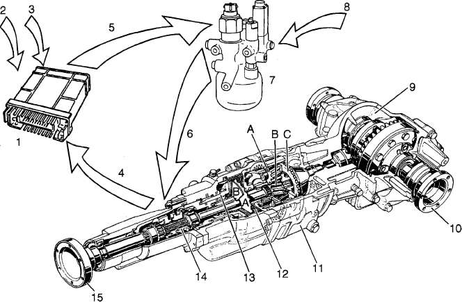
Drive system VISCOMATIC
clutch
To Alfa
Romeo
 became between the two axles a
Drehmomentverteiler also became between the two axles a
Drehmomentverteiler alsoelectronic control of type
VISCOMATIC® assigned, as well as a rear differential type Torsen (basic
relationship 4: 1).
With ideal adhesion conditions
of the four wheels the drive is made by the front wheels. When revving the
wheels up at the front axle, the VISCOMATIC plant distributes the drive
torque to the rear axle.
The Kontrollogik takes over the
optimal distribution of the torque, that to the rear axle depending upon
driving condition is transferred (drive torque, vehicle speed, guidance
angle and the slip between in front and in the
back). |
||||||
|
|
||||||
 |
||||||
|
|
||||||
|
1. |
Electronic steering box control of 9
VISCOMATIC system // ^*W
1Q |
Rear gate EN
differential
Flange for left half
wave
Planetary gear
Group of disk clutch
VISCOMATIC
Hydraulic piston for control
clutch
Towing protection
Flange for drive shaft |
||||
|
2. 3rd
4. 5th 6. 7th 8. |
Signals of the steering box
Motronic '“^0
Signals of the steering box ABS
“'i/M~reLC
Signal position of the hydraulic
piston
Control signal for hydraulic
control block
Supply of the hydraulic
piston
Hydraulic control block with
memory |
11.
12.
13.
14.
15. |
||||
|
Supply hydraulic control block
(of the hydraulic guidance pump) |
||||||
|
11 |
||||||
|
|
||||||
 |
 |
|||||
|
|
||||||
|
|
||
|
OVER
EU_____________________________________________VISCOMATIC
VISCOMATIC®
The VISCOMATIC® consists of a
planetary gear and a viscose rayon clutch with hydraulic control. In
addition an appropriate mechanical device makes a switching off for the
power transmission possible, which while towing the vehicle on only one
axle becomes necessary. - _ |
||
|
|
||
 |
||
|
|
||
|
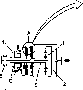
1.
Towing protection
2. Planetray gear
3. Sun wheel
4. Internal gear
5. Interior disk
6.
External disk
7.
Piston with hydraulic
control |
||
|
|
||
|
|
|||||||
|
VISCOMATIC |
|||||||
|
|
|||||||
|
ENTRANCE |
 |
 |
 |
||||
|
Mixture silicone oil/air
without pressure
transferred torque
down |
under pressure
transferred torque highly |
||||||
|
EXIT |
 |
||||||
|
|
|||||||
|
The torque becomes from the planet pinion cage (1)
transferred to the internal gear (2).
The translation from the planet
pinion cage to the internal gear is possible, if the sun wheel f3) -
connected with the clutch and the brake function - also partly
blockieittst. The more largely the blocking, the more largely is the
transferred torque.
The viscose rayon clutch (A) consists of lamellas and a
mixture of silicone oil and air.
The transmission of the movement
in the viscose rayon clutch is reduced by the inconsistency of the oil,
since the oil with air vesicles enriched itself. By the piston (4) the oil
air mixture rising printing values is suspended, thus reduce the air
vesicles, which approach lamellas and it will thus a higher torque
transferred.
With the loosening of the clutch
by the piston (4) the lamellas are pressed apart with the pressure of
warmed up air and the torque which can be transferred reduce.
Each position of the piston,
steered of an electrical valve and the respective pressure in the
hydraulic system steers thus the torque which can be
transferred. |
|||||||
|
|
|||||||
|
13 |
|||||||
|
|
|||||||
 |
 |
||||||
|
|
|||||||
|
|
||||
 |
VISCOMATIC |
|||
|
|
||||
|
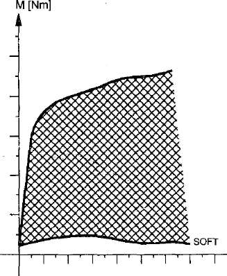
Viscose rayon clutch
The characteristic of the clutch
(transferred torque M/speed difference on) can vary inside a certain range
(see illustration), that by the condition of the maximum transmission is
limited (HARD) and from that the minimum transmission (SOFT). The system
places the clutch into a certain point of function in the work area and
thus arises the transmission of the necessary torque on the rear
axle. |
||||
|
|
||||
|
Piston position max. |
HARD |
On |
||
|
Piston in resting position |
||||
|
|
||||
|
14 |
||||
|
|
||||
|
|
|||
|
VISCOMATIC |
 |
||
|
|
|||
|
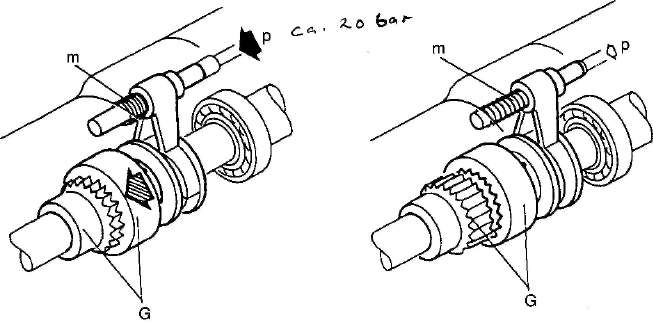
Elimination rear axle
An
appropriate mechanical system (towing protection) makes the complete Auschalten and thus the separation of the
rear axle for the viscose rayon clutch possible.
That is
very important while towing the vehicle on only one axle, since towing with attached axles would damage
the VISCOMATIC clutch.
This
concerns a mechanical device with hydraulic regulation: The clutch {switch
shaft and shift collar) is separated, if the pressure of the tax hydraulic
system of the VISCOMATIC sinks under
a certain level: The interference value varies depending upon
internal friction, temperature
etc.: Indikativer value approx. 20 bar. |
|||
|
|
|||
 |
|||
|
|
|||
|
Switched on clutch
switched off clutch
The
pressure (p) exceeds Kraft that the applied pressure (p) over
cry
Feather/spring (m)
and makes a scarf tet Kraft for the
feather/spring possible (m) not and those
ten the
clutch (G).
Clutch (G) is not switched
on. |
|||
|
|
|||
|
REMARK: When
switching the ignition off the hydraulic system needs a certain time (0.5 to 4 minutes), in order to arrive
under 20 bar.
Therefore some minutes wait,
before the vehicle is towed. |
|||
|
|
|||
 |
|||
|
|
|||
|
|
||
|
VISCOMATIC |
||
|
|
||
|
Hinwels
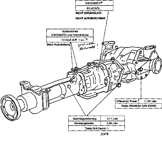
The
transmission system plans the use of 4 different liquids, as represented on the following
pattern: |
||
|
|
||
 |
||
|
|
||
|
16 |
||
|
|
||
|
|
|||
|
VISCOMATIC |
|||
|
|
|||
|
Hydraulic control circuit
A
hydraulic system with high pressure supplies an accumulator, which leads
the necessary liquid quantity with a sufficient pressure to the hydraulic
system. The supply circle is
integrated, and by means of a pump by the crankshaft is propelled
with that the power steering.
This concerns a double pump with 2 different pressure levels for the two
circles:
1. max. 100 bar vane-type pump for the
hydraulic guidance circle and
2. max. 200 bar - piston pump for the
VISCOMATIC circle. |
|||
|
|
|||
 |
|||
|
|
|||
|
1. Ausgleichsbehäiter
2.
Double pump
3. Housing power steering
4. Accumulator with hydraulic control block
VISCOMATIC
5. Clutch VISCOMATIC |
|||
|
|
|||
 |
17 |
||
 |
|||
|
|
|||
|
|
||||||||||||||||||||||||||||||||||||||||||||||||||||
 |
||||||||||||||||||||||||||||||||||||||||||||||||||||
|
|
||||||||||||||||||||||||||||||||||||||||||||||||||||
|
Hydraulic pattern |
 |
|||||||||||||||||||||||||||||||||||||||||||||||||||
|
A =
hydraulic control block B =
VISCOMATIC clutch
(*) von/zu hydraulic guidance
circle |
||||||||||||||||||||||||||||||||||||||||||||||||||||
|
|
||||||||||||||||||||||||||||||||||||||||||||||||||||
|
||||||||||||||||||||||||||||||||||||||||||||||||||||
|
|
||||||||||||||||||||||||||||||||||||||||||||||||||||
|
|
|||
|
VISCOMATIC |
|
||
|
|
|||
|
Description of function
The
supply pump (2), propelled by the Poly V belt of the engine (1), the liquid leads to the hydraulic guidance plant and to the
hydraulic control block of the VISCOMATIC (A). The header tank (3)
with Filterelement in the oil return the reconciliation of the quantity
varying of the oil, which arises during the enterprise, guarantees due to
the work quantity (of memory) and the
thermal extension: Altogether approx. 400 cm3. The sensor (4) the
electronic steering box informs VISCOMATIC (5) in case of of low
oil level. The electrical valve at the accumulator (13) becomes from the
steering box (5) activated and loads
the memory (6) up, whereby a pressure between 82 and 95 bar of a sensor
(7) is held. The memory (6) - capacity 0.5 dm3 - the necessary
energy for the enterprise of the VISCOMATIC guarantees inside the system;
on the supply line a pressure filter (11) is - filter achievement 20 u.m -
that the whole group before foreign particles protects, which could damage
the valves, as well as a return non-return valve (12) that to the pump
prevents the return flow of the oil; a further auxiliary filter (17)
protects the memory load valve (13). The valve (9) the system protects
against positive pressure and opens the circle at 110 bar. The return
non-return valve (10) return flow prevents into the VISCOMATIC group by
the hydraulic guidance
circle.
The
proportional valve for adjustment (8) steer the VISCOMATIC clutch (B) and
regulate the oil flow in the chamber (I) of the piston (14); the oil
pressure in the chamber (II) constantly by the memory one maintains:
therefore becomes on varying the quantity led into the chamber (I) shifting the piston and thus varying
the stiffness of the clutch reached. The function of the valve follows in the
detail:
A. Valve with a certain electric
current supplies: Liquid quantity to the chamber (I) of the
piston
b: closed valve
C: Discharge the chamber (I) from
the piston to the container - with started engine -
D: Discharge the chamber (I) of
the piston - with turned off engine: It becomes a further
river the oil reservoir in the memory (6) and in the chamber (II) reached,
so that the whole plant is emptied.
 |
|||
|
|
|||
|
The
pressure in the chamber (II) switching on of the clutch (towing protection
on 16 controls): If the pressure sinks, scolded the
clutch mechanically the whole group of clutch rear differential out.
The valve
(15) - calibrated on 102 bar - for the automatic exhaust of the plant one
uses (for further details see „exhaust
of the circle "). |
|||
|
|
|||
|
; &g&, &*rw^ |
|||
|
|
|||
|
|
|||||||||||||||||||||||||||||||||||||||
|
VISCOMATIC |
|||||||||||||||||||||||||||||||||||||||
|
|
|||||||||||||||||||||||||||||||||||||||
|
Supply pump |
|||||||||||||||||||||||||||||||||||||||
|
|
|||||||||||||||||||||||||||||||||||||||
|
 |
||||||||||||||||||||||||||||||||||||||
|
|
|||||||||||||||||||||||||||||||||||||||
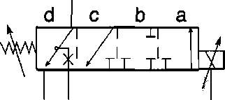
|
Hydraulic control block
In a
building group all valves and components of the hydraulic system are accommodated for the controlling of the
VISCOMATIC clutch. |
|||||||||||||||||||||||||||||||||||||||
|
|
|||||||||||||||||||||||||||||||||||||||
 |
1. Accumulator
2.
Pressure sensor
3.
Speicherladeyentil
4. Hydraulics proportional valve
5.
Pressure filter
cartridge
6. Return non-return valve
7.
Return non-return
valve
8. Relief valve
9. Auxiliary filter |
||||||||||||||||||||||||||||||||||||||
|
|
|||||||||||||||||||||||||||||||||||||||
|
|
||
|
VISCOMATIC_________________________________________________IBÖ
SSI
Exhaust of the hydraulic
system VISCOMATIC
The
exhaust of the circle is made by
an appropriate valve inside the device,
and is not thus not accessible and not adjustable.
The
exhaust is to be accomplished only with ALFA ROMEO the TESTER: This
procedure plans the start of the
engine, whereby this is brought to 2000 revolutions; then sends a
controlling of the tester a constant river of 450 mA to the proportional
valve and controls according to also the memory load valve,
increases the pressure of the circle over the maximum operating values, whereby
the bleed valve is opened (on 102 bar calibrated) and lets to the
container air collected in the plant to stream out. In the case of
completion of this procedure it is possible to examine with the tester
whether the plant without air
is. |
||
|
|
||
 |
||
|
|
||
|
|
||
|
V1SC0MATIC |
||
|
|
||
|
Electronic
Kontrollanlage
The electronic steering
box VISCOMATIC controls „the slip " between the foremost and
rear axle and limits it at certain values, depending upon the
different driving conditions. These conditions are inferred by several
sensors or taken up by other plants (ABS or Motronic). The
steering box steers therefore the valves, which regulate the
function of the viscose rayon clutch. The operation diagramme
points this out schematically: |
||
|
|
||
SAFETY I RELAY
| PRESSURE HYDRAULIC SYSTEM SIGNAL LAMP DISTURBANCE PLUNGER LIFT CLUTCH ANSCHLUSSTECKER ALFA ROMEO
TESTERS GUIDANCE ANGLE HYDRAULIC PROPORTIONAL
VALVE STOOD HYDRAULIC OIL MEMORY LOAD
VALVE STEERING
BOX
VISCOMATIC® ^-■
WHEEL SPEED BUTTERFLY VALVE ANGLE ENGINE NUMBER OF
REVOLUTIONS MANIPULATION
BRAKE SWITCH ON REVERSE
GEAR |
||
|
|
||
|
|
|||
|
VISCOMATIC |
 |
||
|
|
|||
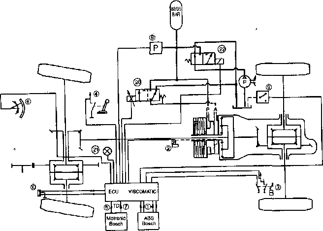
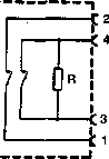
Sensors
and Kontroilogistik |
|||
|
|
|||
|
The
Kontrollogistik of the steering box, which steers the hydraulic system of
the VISCOMATIC, plans the
availability of a series of data, which are inferred partly directly by
sensors and are partly
again-processed. In accordance with these parameters the steering box
regulates the electrical valve (20) with a variable river (from 400 to
2300 mA) proportional for the speed of the piston, the connection of the
clutch varied and thus the allocation of the transmission moment on the
rear axle.
The
directly inferred data are the following:
- The number of revolutions of the four wheels.
The four data become from the abs system (1) taken
over.
- The Drehzahi of the engine by the steering box
Motronic (7).
- The opening angle of the butterfly valve (in
the percentage), by the steering box Motronic (5).
- The guidance angle
(6), given by a specific sensor in the steering element
housing.
- The position of the piston (2), whose stroke
from 0 to 5 mm can vary; the position of maximum resetting is recognized, if the
river of the electrical valve (20) is with 900 mA.
- The pressure of the hydraulic system of the
memory, measured of the sensor (8); this pressure is held between 82 and 95 bar by
a memory load valve (22).
- A signal during operation of the brake
(3).
- A signal when switching on of the reverse
gear (4) on.
- Sensor oil level (9). |
|||
|
|
|||
 |
|||
|
|
|||
|
|
||
|
1B^1 SO”
_________________________________________________VISCOMATIC
The
system is with a control light (21) and with the possibility for the
diagnosis with the Alfa Romeo tester
(10) equipped.
REMARK:
The function of the steering box is dependently on the voltage level of
the battery, under 9 V scolded
themselves it not.
There are
parameters, which are not inferred directly by the sensors, but by the
steering box in accordance with special logics to be calculated, which are
described as follows:
 |
||
|
|
||
|
24 |
||
|
|
||
|
|
|||
|
VISCOMATIC |
1 |
||
|
|
|||
|
Function logic of the
system
The most
important logics are described here, which are regulated by the software of the
steering box, in order to regulate
the allocation of the torque by the clutch. |
|||
|
|
|||
|
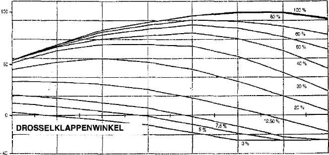
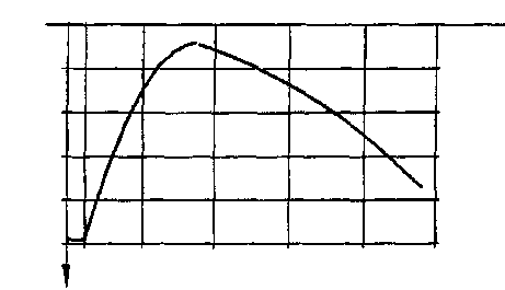
Drive torque
The
drive torque at the wheels is calculated by the product of the torque,
which is delivered by the engine for
the entire drive. It is
indicated as percentage of
its maximum value. The torque
delivered by the engine is inferred from the curves of the load diagram,
which is stored in the steering box. Each value of the number of revolutions and
percentage of the butterfly valve opening, correspond to a value of
the torque, which is delivered by
the engine.
The total
drive is calculated against it by
the relationship between engine number of revolutions and number of revolutions of the front
axle. |
|||
|
|
|||
|
DRIVE TORQUE
(%) |
|||
|
|
|||
 |
|||
|
|
|||
|
0
1000
2000
3000
4000
5000
6000
7000 |
|||
|
|
|||
|
ENGINE SPEED
(1/min) |
|||
|
|
|||
|
|
||||
 |
VISCOMATIC |
|||
|
|
||||
|
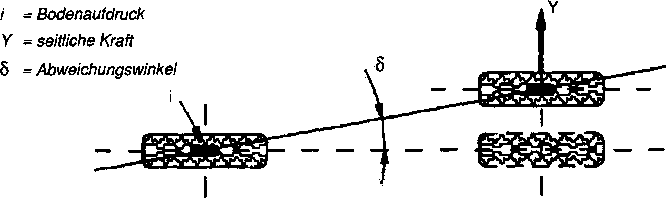
Slip between foremost and rear axle
By slip one understands the
proportional difference of the speed of the front axle opposite the rear
axle.
Front axle - rear axle x 100
Slip = speed difference
-------------------------------------------------
Rear axle
In order to be able to have the
value of the slip due to revving the tires up, one must take the kinetic
slip.
This kinematic slip is the
result of the over each other setting of the two conditions:
First is due to the variability
between the turning extent of the tires due to for example wrong printing
values, or different wear condition, unequal tire load, presence of the
spare wheel etc.
The second condition, which
determines the kinematic slip, is the different rotating speed of the
axles, which arises in the curve. The C.I.R. (center of the momentary
turn) shifts depending upon guidance angle, in addition, depending upon
deviation of the tires. |
||||
|
|
||||
 |
||||
|
|
||||
|
Deviation of a Rads with tires under a lateral
load. |
||||
|
|
||||
|
This angle results from
different variables, how: Kind of tire, pressure of the tire, trap
coefficient.
In addition it is directly
proportional to the centrifugal energy (square of the radius speed,
guidance radius and measures of the vehicle) and the torque used at the
wheel; it is opposite proportional against it to the vertical load on the
wheel.
The steering box regards only
the kinematic effects and thus only the speed parameters and guidance
angles. |
||||
|
|
||||
|
26 |
||||
|
|
||||
|
|
||||
|
VISCOMATIC |
 |
|||
|
|
||||
|
-
With standard speed the speed increase increases the deviation forward.
That calls (see illustration) a
shifting „of the center of the turn " (+) forwards, with from-following reduction of the kinematic
slip. |
||||
|
|
||||
 |
DRIVING
DIRECTION |
|||
|
|
||||
|
On
the other hand the situation turned around when backing up: Shifting „the
center of the turn " (+) causes an
increase of the kinematic slip. |
||||
|
|
||||
 |
DRIVING
DIRECTION |
|||
|
27 |
||||
|
|
||||
 |
 |
|||
|
|
||||
|
|
|||
 |
VISCOMATIC |
||
|
|
|||
|
There are tables over the normal
trip and over the reverse movement. The kinematic slip is reduced as
described with increase of the deviation (standard speed) and with reverse
movement the slip increases.
The evaluation of the kinematic
slip due to the curve movement is read from the system, and compared with
the stored tables in the program of the steering box - in that the
important data are contained -. |
|||
|
|
|||
|
Positioning the piston
In order to guarantee that the
distribution of the course torque on the two axles is made in shortest
time it is before-shifted, the regulation, as the piston is positioned
depending upon course torque. From this position one proceeds, in order to
make the definite attitude concerning the slip, if this
arises. |
|||
|
|
|||
|
STROKE PISTON (%)
100} |
|||
 |
* - TRACTION POWER |
||
|
|
|||
|
In order to guarantee a good
function of the system, for example when fast starting, with which the
taken values of the important parameters close the piston during
pre-setting, other signals are not considered, which would cause
mismatching partial openings of the piston. If the system would consider
for example small guidance angles at low speeds, the piston is opened,
whereby thereby disturbing conditions would arise when
driving. |
|||
|
|
|||
|
28 |
|||
|
|
|||
|
|
||||
|
VISCOMATIC |
||||
|
|
||||
|
Attitude of the course slip
With special circumstances the
system does not intervene also at important slip values.
For
example a high slip value is certified at low speeds. One avoids in such a way that the attitude of
small measuring errors of the speed and irregularity of the road
surfacing, although small, is affected, which would be important however in this
case.
For the
same reason the certified slip value increases, if the course torque is limited. |
||||
|
|
||||
|
CERTIFIED
SLIP
 |
||||
|
|
||||
|
VEHICLE
SPEED |
||||
|
|
||||
|
CERTIFIED
SLIP |
||||
|
|
||||
 |
COURSE
TORQUE |
|||
|
|
||||
|
29 |
||||
|
|
||||
 |
 |
|||
|
|
||||
|
|
|||
|
16 |
VISCOMATIC |
||
|
|
|||
|
Attitude of the transverse slip of the rear axle
The closing differential (Torsen
4: 1) in the rear axle causes that in the curve the internal rear wheel is
loaded with a quadruple higher torque. This wheel tends to revving up,
since in the curve also the vertical load sinks. In this condition the
slip between the two axles to inappropriate way and the piston reduce
tended to open and lead to an allocation of the torque between the two
axles with increase of the average speed of the rear wheels, which brings
driving difficulties with itself. In this case a function intervenes,
which adds itself to the difference between the real slip and the
certified and is lost due to revving the internal rear wheel up. Therefore
the piston remains closed due to the signal by this wheel, whereby the
movability of the vehicle is improved. |
|||
|
|
|||
|
Attitude of the sliding operating slip
With sliding enterprise the
exhaust brake works the vertical load on the rear axle, which can rev up
therefore easily particularly on the front axle, on the other side sinks
in this condition. |
|||
|
|
|||
|
REMARK: If the speed of the rear axle more highly than those
the foremost
axle is, takes the slip negative values.
The certified negative slip at
low speeds is therefore for the same reasons higher, from those, as seen,
at low speeds the course slip is high. At medium speeds the value of the
certified slip is limited, since a good torque value reduces the
Untersteuern (with bad adhesion), which arises in the curve particularly
on the front axle on the rear axle.
At high speeds the threshold
increases strongly, in order to let the exhaust brake affect only the
front axle and to thus guarantee a good driving
stability. |
|||
|
|
|||
 |
* - VEHICLE
SPEED |
||
|
|
|||
|
CERTIFIED SLIP (NEGATIVE) |
|||
|
|
|||
|
30 |
|||
|
|
|||
|
|
|||
|
VISCOMATIC |
1 |
||
|
|
|||
|
Attitude when braking
The
system refers to the rear axle. When braking the real speed of the rear axle is not considered, if this by a
delay over 0,24 g is determined. At higher delay values the datum speed
sinks not in accordance with the
real process separates gradually.
The
VISCOMATIC normally intervenes, until the difference between the effective
speed and the delimitation
speed does not exceed a certain threshold value (also
function of the guidance angle: This threshold is limited with low
guidance angles). Above this threshold the VISCOMATIC does not intervene
during braking, except with exceptions, whereby malfunctions with the abs
plant are avoided (for further
details see „brake system ABS 4WD "). |
|||
|
|
|||
|
|
|||
|
CD
r \ 3 |
|||
|
|
|||
 |
|
||
|
|
|||
|
|
|||
|
|
|||
|
|
|||
|
|
|||
|
■ |
|||
|
|
|||
|
|
|||||
|
VISCOMATIC |
|||||
|
|
|||||
|
Description of function
The system of the VISCOMATIC is administered by the
controller N 75.
The permanent voltage supply of
the controller is made via the battery, by the protection F1 (7.5 A) -
additional fuse housing G 2 -, on the controller pin
1.
Against the pins rests
20 and 25 of the controller measure. The information
„ignition " comes over the protection F 4 (3 A) - G 2 - on the controller
pin 14.
The main supply for the controller is made over the change
relay 1104. |
|||||
|
|
|||||
|
Relay function: no
Fehler>
with Fehler> the
sensors: |
After the info. „ignition " over
pin 14 at the controller, this accomplishes a Eigendiagnose
Relay becomes over the Kl. and
supplies now the controller excites 86 with 12 V via Kl. 30 over Kl. 87,
protection F 5 (10 A) - G 2 - at pin 13 with battery
voltage.
Indicator light becomes of relays
Kl. 87a with tension supplies and shines.
Guidance protractor L 53
1 = 5 V
2 = signal voltage - >
pin 3 Stg
3 = measures
 |
||||
|
|
|||||
|
Oil pressure sensor L 56 |
|||||
|
|
|||||
 |
A = measures of B = 5
V
C = signal
voltage |
Pin 18 Stg |
|||
|
|
|||||
|
Sensor plunger lift L 55
Pin 1 = 5 V - ►
Pin 2 = signal voltage - *■
pin 16 Stg
Pin 3 = measures
Sensor oil level L 54
Switch reverse gear: H 2 informs
the controller at pin 10 with 12 V that the reverse gear is
inserted.
Brake pedal switch H 3
1 =12 volt
2 = pedal pressed - *■
pin 23 Stg “h|
4 = pedal not pressed - ► pin 22 Stg
  |
|||||
|
|
|||||
|
|
||
|
HM3Ü_________________________________________________VISCOMATIC
Except
of the appropriate sensors, the steering box receives N75 information from
the abs system and Motronic system:
The pins 7.8.9 and 21 of the N75 are connected with the steering box ABS N51, from
which they receive proportional signals for the speed of the 4 wheels; at
the pins 15 and 12 comes against it from the steering box Motronic S11 the signals of the butterfly valve
angle and the engine number of revolutions.
The logic
before shown processes the steering box the control signals of the
actuators, which are controlled
accordingly: From the pin 11 the signal “Duty Cicle” (variable, 250
cycles per second) comes,
which the proportional valve inside the hydraulic control block M25
steers, of the pin 24 comes a
continuous signal 12 V to the controlling (ON OFF) of the memory load valve of the group of
M25.
Pin 4 and 5 for the diagnostic
possibility (plug T1) - line K and L - to the connection with Alfa Romeo the TESTER. Pin 19 12 a V-signal
for the control light of on-board board C10 in case of of stored
disturbances. |
||
|
|
||
|
34 |
||
|
|
||
|
|
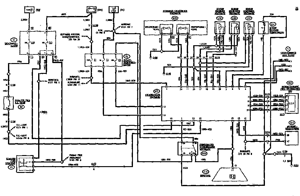
||||||||||||||||||||||||||||||||||||||||||||||||||||||||||||||||||||||||||||||
|
VISCOMATIC |
||||||||||||||||||||||||||||||||||||||||||||||||||||||||||||||||||||||||||||||
|
|
||||||||||||||||||||||||||||||||||||||||||||||||||||||||||||||||||||||||||||||
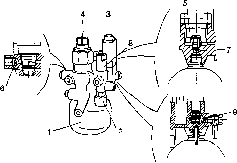
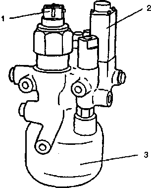
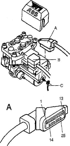
|
Components of the
system
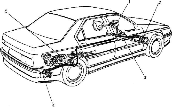
Electronic steering box
(N75)
It is under the middle
console, in the shown position: |
||||||||||||||||||||||||||||||||||||||||||||||||||||||||||||||||||||||||||||||
|
|
||||||||||||||||||||||||||||||||||||||||||||||||||||||||||||||||||||||||||||||
|
PIN-OUT steering
box:
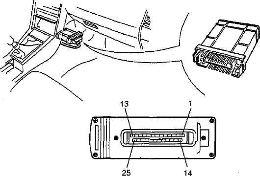 |
||||||||||||||||||||||||||||||||||||||||||||||||||||||||||||||||||||||||||||||
|
|
||||||||||||||||||||||||||||||||||||||||||||||||||||||||||||||||||||||||||||||
|
12 V-supply (+15)
Signal
butterfly valve angle (of
Motronic)
Signal
plunger lift
Supply
+ 5 V for the sensors
Signal
pressure hydraulic system
Signal
for signal lamp on-board board (12
V)
Measures of achievement
circles
Signal
speed wheel in front left (of
ABS)
Signal released brake
pedal
(12 V)
Signal
pressed brake pedal (12
V)
Signal
control memory load valve (12V)
Measures of system
circles |
|||||||||||||||||||||||||||||||||||||||||||||||||||||||||||||||||||||||||||||
|
|
||||||||||||||||||||||||||||||||||||||||||||||||||||||||||||||||||||||||||||||
 |
||||||||||||||||||||||||||||||||||||||||||||||||||||||||||||||||||||||||||||||
|
|
||||||||||||||||||||||||||||||||||||||||||||||||||||||||||||||||||||||||||||||
|
|
|||
|
VISC0MAT1C |
|||
|
|
|||
|
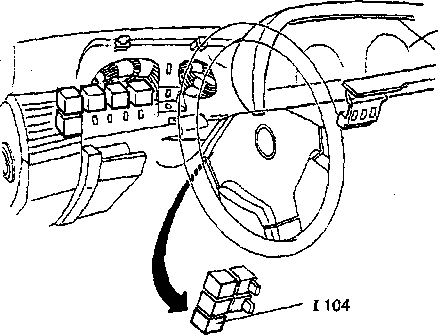
Safety external switch (1104)
The
steering box controls and regulates the supply of the achievement circles
by an appropriate external switch, which interrupts the supply at the
actuators and thus the system switches
off, if it comes to disturbances.
The external switch is on the
right side behind the combination instrument. |
|||
|
|
|||
 |
|
||
|
|
|||
|
1104 safety external switches
for steering boxes VISCOMATIC |
|||
|
|
|||
|
|
|||
|
VISCOMATIC |
.1 |
||
|
|
|||
|
Stop light switch (H3)
The same
switch as for is the circle of the stop lights, 2 signals by the
controller is processed: approved and
pressed brake pedal.
Reverse gear switch
(H2)
The same
switch as for is the circle of the backup lights, from which from the
signal of the switched on reverse gear
proceeds.
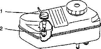
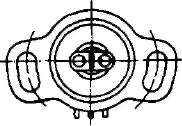
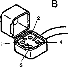
Sensor oil level (L54)
It is on
the expansion tank for the hydraulic guidance plant and VISCOMATIC (for
further details see “power
steering”). |
|||
|
|
|||
 |
|||
|
|
|||
|
1. Sensor
2. Float |
|||
|
|
|||
|
This
concerns a switch (N.C), which is connected with a float, that opens it, if the level of liquid the “MIN” - value
reaches. |
|||
|
|
|||
|
|
|||
|
1. |
VISCOMATIC |
||
|
|
|||
|
Sensor plunger lift (L55)
The
sensor is in the VISCOMATIC group and is bound with a linkage at the
pistons. This concerns potentiometer, that the steering box a signal
proportionally to the position of the piston sends (supply voltage 5V,
Rmax 2 kΩ). |
|||
|
|
|||
 |
|||
|
|
|||
|
1. Sensor plunger lift
2. Group VISCOMATIC |
|||
|
|
|||
|
The
measuring of this sensor takes place automatically: Each time, if the
attitude valve at minimum value (<
900 mA) stays a certain time long, this reference value is taken as 0-Weg,
while the final stroke of the piston is accepted as maximum way
(5 mm). |
|||
|
|
|||
|
|
||||
|
VISCOMATIC |
||||
|
|
||||
|
Sensor guidance angle
(L53)
This
concerns potentiometers, which is accommodated in the steering housing. It
sends a proportional signal
to the steering box to the guidance
angle (sign „+ " steering angle right, signs „- “steering angle
left).
- Supply voltage = 5 V
- Rmax = 1 kß
- Range guidance angle = 330° (+
3%)
 |
||||
|
|
||||
|
1. Steering housing
2. Sensor |
||||
|
|
||||
|
Measuring of the sensor
- The vehicle with wheels on straightforward and
steering wheel position - to GUIDANCES FOR the REPAIR see
microfiche
- The sensor into the steering housing do not
build, which plugs attach.
- Attach ALFA ROMEO the TESTER to the
steering box VISCOMATIC.
- The key to trip set and with the tester examine
that the tension of the output signal of the sensor is with approx. 2,5 V: If
the tension should be approx. 0 V, that |
||||
|
|
||||
|
Element of the sensor around
180° turn. |
||||
|
|
||||
 |
 |
|||
|
|
||||
|
It
fastens the sensor on the steering housing, makes certain that the
steering element stands in
the position guidance center and is
the tension signal with 2.5 ± 0,04 V.
- The
correct function examined, as the steering wheel is turned and at the
right attack is kept two seconds
long, then likewise at the left attack and with the tester to examine that no error is
indicated. |
39 |
|||
|
|
||||
 |
||||
|
|
|||
|
VISCOMATIC |
|||
|
|
|||
|
Electrical valve hydraulic control block (M25)
In the
hydraulic control block (see hydraulic control circuit) are two electrical
valves, which are steered by the
electronic steering
box. |
|||
|
|
|||
|
1. Hydraulic proportional
valve
2. Memory load valve
3. Memory |
 |
||
|
|
|||
|
Memory load valve
This
concerns a valve ON/COFF that supplies the memory and holds the pressure between 82 and 95 bar, during the normal
enterprise of the vehicle.
NOTE:
The valve is only also activated
at engine number of revolutions over 400 rpm and at speeds over approx. 4 km/h. |
|||
|
|
|||
|
40 |
|||
|
|
|||
|
|
|||
|
VISCOMATIC. |
|||
|
|
|||
|
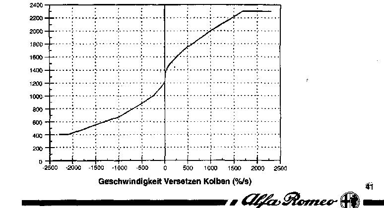
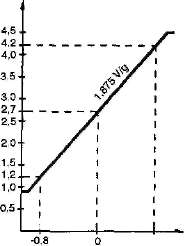
Proportional valve river
attitude
This
concerns a servo valve that a liquid
quantity proportional to the excitation stream lets flow through. In this way the
Kolbenkammer with the transfer of the piston is varied. The signal that
the steering box sends to
this electrical valve is a variable “Duty Cicle” (12 V, max. 2.3 A)
- see illustration. |
|||
|
|
|||
|
REMARK: |
With a
direct supply (12 V) the valve was damaged, therefore the system interrupts the
supply, if this tension continues
continuously longer than 100 ms. |
||
|
|
|||
|
Characteristic curve of
the valve
With a
certain river at the electrical valve one achieves a certain liquid
quantity, which the pistons from a
position to the other one transferred and so the translation about
a certain representation with
one „talk " slip to another with one „desired " slip brings, which was
calculated by the steering box.
Excitation stream (mA) |
|||
|
|
|||
 |
|||
|
|
|||
|
|
|||
|
1 |
VISCOMATIC |
||
|
|
|||
|
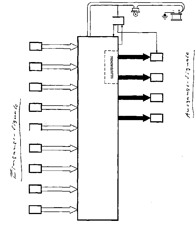
Diagnostics of the
system
A
complex self diagnostic logic controls the complete system in each
moment:
- Supplies of the
circles of the system and the achievement circles
- Examination of the
internal memory (only with the initial test).
- Examination of the detailed signals (range
of the certified values, stages of varying and plausibility)
analogisch, as digital.
- Examination of the
control signals of the actuators.
If an
error or a disturbance is present, this information - by an appropriate
“error code” - is transmitted to the error memory (RAM) of the steering
box; at the same time the disturbance
signal lamp on on-board board lights up and the fail-safe program is
activated.
More than 70 different error
codes can be inferred!
The
disturbance signal lamp on on-board board shines for 1 -2 seconds when
starting during the initial at the
beginning of the system on {storages and internal
components).
If no
errors arise, expire them, if the controller infers against it errors,
remains the signal lamp
on.
The
fail-safe program depends on the taken error: If an error arises with a sensor, which does not affect the whole
system completely, the signal value is corrected this sensor with a reference value („Recovery
").
If
against it an important disturbance of the system is inferred, like for
example at the hydraulic system, the
system becomes cut out. If the errors in addition the achievement
circle concern scolded the steering box with the safety external switch
the system out.
All stored Fehler-die „current " as well as „the previous "
can only with the Alfa
Romeo tester to be read and
deleted.
In order
to delete and the fail-safe program switch the signal lamp off, it is
sufficient to switch the steering
box off (keys on STOP). If during restarting the errors is no longer
present, the signal lamp does not light up any longer and the fail-safe program is not activated. The
before taken up error remains nevertheless stored.
For each
error code a speedometer is intended: With the occurrence of an error this
counter is placed to its maximum
value (255): With each restart the counter is lowered around 1, if the
error is no longer present; In this way an error is cleared after 255 restarts, if it arose coincidentally
and does not occur any longer, from the memory.
Likewise the delete operation
brings all counters to Rome EO testers with the ALFA
zero, |
|||
|
|
|||
|
|
||
 |
||
|
|
||
|
|
|||
|
1 |
ABS |
||
|
|
|||
|
General description „ABS "
The 164 4x4 is equipped with the
electronic anti-skid system (ABS). This concerns a specific version for
this vehicle with all-wheel drive. VERSION with 6 sensors and 4
channels.
Speed sensors
The four sensors, which are
assigned at the four wheels, indicate the respective wheel speeds to the
electronic steering box - they were again designed.
Sensors of the crosswise and longitudinal
acceleration
These two sensors were added, in
order to infer additional parameters, which are needed by the specific
Kontrollogik the braking. This concerns electromechanical devices, which
are led during accelerations (+) to react and their value to the
electronic steering box.
REMARK: In the previous versions
these sensors were simple on off switches. In this case it bargains for
around hall effect sensors,
proportional signal to the taken
speed pass on: Makes possible for the operating logic to activate
different behaviors depending upon acceleration borders, while before only
one interference threshold could be considered.
Clutch switch
Makes possible the information to
the steering box over the interrupted force river between engine and
transmission, in order to be able to correct according to the braking in
this condition.
Function high-speed no-load operation (LDA)
ABS is in connection with the
MOTRON IC system. When strong decelerations the vehicle and on the basis
of high engine speeds, due to the drive system the engine would tend when
braking to turning off. The steering box ABS informs the steering box in
this case MOTRONIC. In addition the engine brake effect became effective
also at the rear wheels, which would brake more than necessarily. For the
avoidance of the over braking of the rear wheels, the logic of the system
seizes „opening of the no-load operation automatic controller
".
Signals for the VISCOMATIC system
The steering box ABS sends the 4
Geschwindigkeitssignale of the wheels to the VISCÖMAT system, which uses
these information, in order the drive logic to define (see system
VISCOMATIC). |
|||
|
|
|||
|
|
|||
|
ABS |
1J |
||
|
|
|||
|
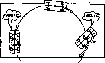
Interference logic for the version 4x4
With the special version „" the
ABS all conventional interference logics receives 4 x 4 from the brake
system, in order to prevent the blocking of the wheels.
The presence of two additional
sensors (the two accelerometers) has the development of other specific
logics for 4 x 4-Fahrzeuge “ÜÜrffl (§3* in particular made
possible.
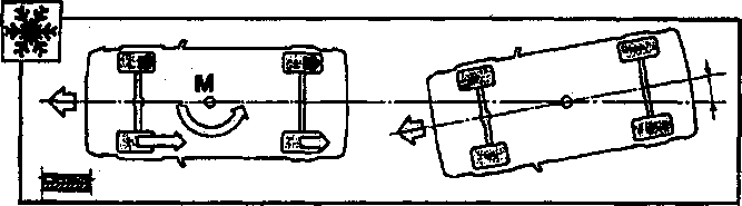
1. Different adhesion of the wheels
In case of of different
detention condition between the right and left side of the vehicle (e.g.
layer of ice…), a different reaction at the ground at both sides arises:
From it results one M-moment, which is called „craving " and which brings
vehicle to the rotation around the point „M ". |
|||
|
|
|||
 |
|||
|
|
|||
|
With vehicles with only
two drive wheels this disturbance can be reduced easily by the
conventional abs system, the brake pressure accordingly modulated and in
particular at the demanded drive wheel reduced, as well as owing to the
function „SELECT low " (clocked controls at the rear wheels). A drastic
reduction of the yaw moment makes M. possible. |
|||
|
|
|||
 |
|||
|
|
|||
|
'*
€Zp&>®*me*'% |
|||
|
|
|||
|
|
||
|
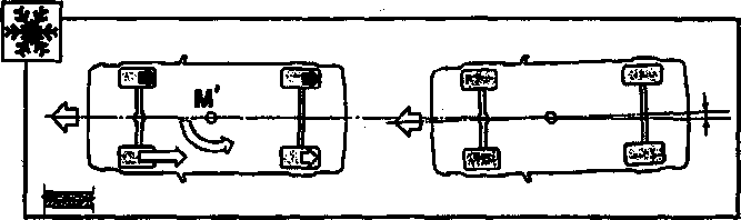
With vehicles with
four drive wheels craving is
strengthened by the larger reaction of the two responsible wheels, caused in the special by the viscous drive of the
rear wheels: From this an
increase of the yaw moment M takes place in relation to the
versions with front wheel drive. |
||
|
|
||
 |
||
|
|
||
|
The
specific logic of the ABS intervenes thus, as the increase of the
pressure on the wheels is affected with higher adhesion, and so the yaw
moment value M is strongly reduced. Thus driving safety of the vehicle is
improved, in the case of the different adhesion between the two sides of the
vehicle. |
||
|
|
||
 |
||
|
|
||
|
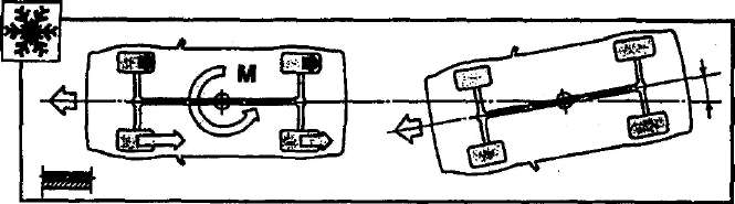
2. Curves with high speed (also with good
adhesion)
The
Kontrollogik of transverse acceleration intervenes, if the sensors infer different speed between the wheels of the two sides,
however impossible in case of a curve with high speed. The vehicle
would override, since the ABS would
lower the pressure in the two outer wheels too strongly. The reduction of
the yaw moment M would let the over-regulation effect M become
stronger, also with easy brakings. |
||
|
|
||
|
46 |
||
|
|
||
|
|
|||
|
ABS----------------------------------------------------------------------------------\
imm &u
The
sensor of transverse acceleration indicates the actual situation to
the steering box, which leads a
certain brake pressure, above all to the rear. In addition the abs
function is ahead-sent „",
which intervenes and in advance „releases the brake pressure
". |
|||
|
|
|||
 |
|||
|
|
|||
|
3. Bad adhesion with acceleration
(or in the sliding
enterprise)
For
example when driving a curve out with bad adhesion all four wheels have a
certain slip. The datum speed value,
which is normally calculated, is very inaccurate and causes for one „release
effect " of the brake printing with from-following adhesion problem. This
value is thus corrected, as acceleration or slowing down of the
sensor longitudinal acceleration is measured. One reaches so a braking with limited
slip.
4. Snaps minimum number of revolutions
(high-speed no-load operation)
With
vehicles with four drive wheels, a delay of the rear wheels when
braking or when simple slowing down due to the engine brake, which brake from-following more than necessarily
„", increases. This situation
is strengthened only partially by the VISCOMATIC clutch. The clutch
remains closed in some cases „" and leads a certain torque to the rear
range (for further details see „VISCOMATIC "). With bad adhesion, this
problem solves the function „high-speed no-load operation ", which
eliminates the effect of the engine brake at the wheels. The sensor of the
longitudinal acceleration infers the
range of the slowing down and with bad adhesion (it intervenes the
ABS), sends it a signal, „from LDA ", to the steering box of the Motronic
that the number of revolutions amends
or lets the engine „more softly " to the idling speed
come.
REMARK this function
however interrupted:
- pressed clutch pedal (situation by the
appropriate switch on the clutch pedal one takes).
- Speed of the vehicle
too small
- Engine speed already
with minimum value (no-load operation) |
|||
|
|
|||
|
47 |
|||
|
|
|||
 |
 |
||
|
|
|||
|
|
|||
|
Localization components of
the system |
|||
|
|
|||
 |
|||
|
|
|||
|
1.
Inductive sensors vehicle
speed 4.
2.
Clay/tone wheels 5.
3. Hydraulic group with abs
tax
housing 6. |
Control light
Sensors
along and transverse
acceleration
Switch clutch
pedal |
||
|
|
|||
|
48 |
|||
|
|
|||
|
|
|||||
|
ABS |
|||||
|
|
|||||
|
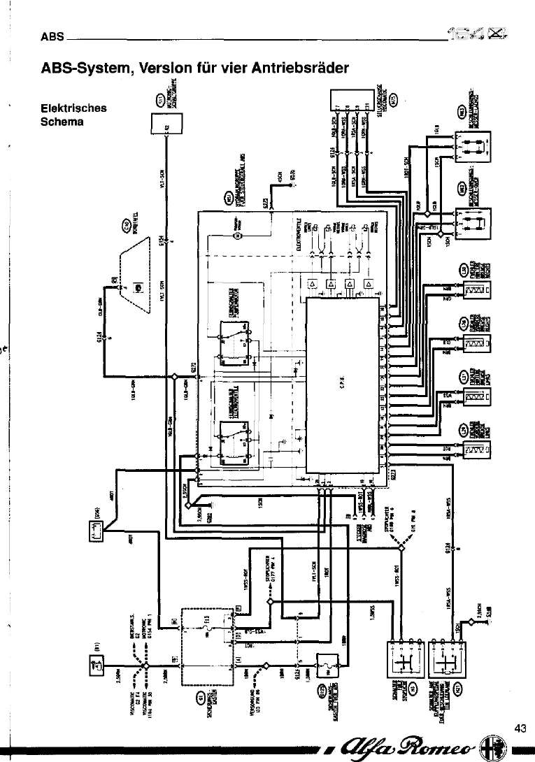
Hydraulic's group with steering box ABS
This concerns the same building
group („hybrid "), which was already installed in 164 the super. In a
block the electronic steering box with hydraulic's group and 4 electrical
control valves for the individual wheels. |
|||||
|
|
|||||
 |
 |
||||
|
PIN-OUT steering box; Plug „A " (G273) |
|||||
|
1 2 3 |
Signal
lamp disturbance
Switch brake pedal sensor
longitudinal acceleration |
||||
|
4. -
5. Switch clutch pedal
6. Signal rear wheel left for
VISCOMATIC
7. Signal front wheel left for
VISCOMATIC
8. Signal front wheel left
(measures)
9. Signal rear wheel left.
10.
Signal front wheel rh
(measures)
11. Supply for sensors
acceleration
12. Signal front wheel
rh.
13. Measures for sensors
acceleration
14. Sensor transverse
acceleration
15. Diagnostics line K
16. Diagnostics line L 17. --
18. Signal front wheel rh for
VISCOMATIC
19. Signal rear wheel rh for
VISCOMATIC
20. Signal front wheel
left.
21. Signal rear wheel left
(measures)
22. Signal rear wheel rh
(measures)
23. Signal rear wheel rh
24. “
25. Signal LDA to the
Motronic
PIN-OUT hydraulic's group:
Plug „B " (G272)
1. Supply (with 10 A-protection) Kl.
15
2. Direct supply of battery
3. Measures
4. Signal lamp
disturbance
Ground connection „C " (G275) |
|||||
 |
|||||
 |
49 |
||||
 |
|||||
|
|
|||||
|
|
|||
|
ABS |
|||
|
|
|||
|
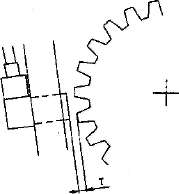
Sensors speed
The four sensors are on the hubs
of the four wheels in the range of the clay/tone wheels - 44 teeth -. The
sensors were again designed. |
|||
|
|
|||
 |
|||
|
|
|||
|
Air gap value between wheel and sensor: |
|||
|
|
|||
|
Air gap for front wheels air gap
for rear wheels |
T = 0.55 - p 1.2 mm T = 0.6
f1,3mm |
||
|
|
|||
|
Clutch switch
This concerns a double N.C. -
Switch (closed), which opens, if the clutch pedal is pressed.
Parallel to the contact a
resistance (R = 4.22 kß) is, which serves for the examination of the
electric circuit. |
|||
|
|
|||
|
Electrical pattern
pin 1 not attached
pin 2 not attached
pin 3 measures
pin 4 signal under tension to the steering box
closed contact < 1.25 V
opened contact > 1.25 V
< 3.00 V
separated switch > 3.00 V
< 4.50 V |
 |
||
|
|
|||
|
50 |
|||
|
|
|||
|
|
|||||||||
|
abs____________________________.
----------------------wmrn
m^
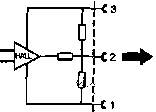
Sensors acceleration (crosswise and lengthwise)
This
concerns electromechanical devices with the principle of the
measures/feather/spring: An
acceleration moves the measures, which act against the feather/spring,
whose movement is inferred by a magnet and by an element with hall effect
is processed, which emits a tension signal corresponding for taken
acceleration. The two, sensors are under the center console, in the
proximity of the Barizentrums of the vehicle. |
|||||||||
|
|
|||||||||
|
TENSION [V] |
|||||||||
|
Electrical pattern |
+0,8 |
ACCELERATION [g] |
|||||||
 |
|||||||||
|
|
|||||||||
|
pin 1 measure
to pin 2 output signal (under
tension), see diagram
pin 3 supply (5 V) |
|||||||||
|
|
|||||||||
|
REMARK: The two
sensors are calibrated in the
structure equal as well as on the same values: The steering box processes the input
values differently, which arrive
at the two pins.
TO THE
AVOIDANCE OF THE MISTAKE, CREDIT THE TWO SENSORS ON THE HOUSING DIFFERENT COLOR
MARKINGS
1.
TRANSVERSE SENSOR OF WHITE HOUSING
2. LONGITUDINAL SENSOR BLACK HOUSING
In
addition the transverse sensor has an arrow, which shows in driving
direction of the vehicle. |
|||||||||
|
|
|||||||||
 |
DRIVING
DIRECTION |
 |
 |
||||||
|
A. Measures
b. Feather/spring
NOTE: |
|||||||||
|
The
sensors contain a magnetic element. Therefore special caution, if in the
proximity with iron-magnetic material one works. |
51 |
||||||||
|
|
|||||||||
 |
 |
||||||||
|
|
|||||||||
|
|
||
|
i |
||
|
|
||
|
Description of function
The
system is administered and steered by an electronic steering box, which
is positioned inside the hydraulic's group of
N51.
The
activation in the circle of the brake assembly is realized by the
hydraulic's group of N51, which control the pressure of the brake fluid
after controlling of the electronic steering box; it contains the
electrical pump as well as the four
electrical valves, one of the brake fluid with the respective
external switch for each wheel
(so-called „4 channel 'version) with respective external switch.
The
supply of the system is made directly from the battery and by ignition via
the protection of the specific
protection G125 (10A).
The four
sensors on the wheels L28, L29, L30 and L31, are connected with the steering box
and send a signal proportionally to
the speed.
The two
acceleration sensors N62 and N63, supplied at the pin 3 with
5 V and measures of the pin a 1,
supply a proportional signal for taken acceleration, which is handed over to the steering box to
the pin with 2.
By the
signal of the switch the information about an arising braking is given to
the brake H3, which steers the stop lights.
The
clutch switch H21 is directly connected with the steering box and
sends a tension signal, which informs
engine and transmission about the separation. The steering box is
connected (pin 25) with the Motronicsteuergerät S11, to which the
demand is given to the
accelerated minimum number of revolutions
(LDA).
LDA = idling speed rise =
high-speed no-load operation.
In addition a connection with
the controller N75 Viscomatic exists for the
transmission
the Geschwindigkeitssignale
of the four wheels.
The
internal self diagnostic system in the steering box announces disturbances
or not correct function over pin 1 to
the appropriate signal lamp of on-board board C10; the same
signal is announced also to errors
in the hydraulic's group - pin 4 of the plug G272
-. |
||
|
|
||
|
|
|||
|
abs_____________________________________________jiöö
m
Same diagnosis
The
available version of the ABS excludes the normal brake system from the
Selbstdiagnose, which holds continuously all components and parameters of
the system under control: in case of of disturbances or bad function
scolded yourself the system automatically out and only the conventional mechanical
servo-supported system is active. This situation is indicated to the
driver by an appropriate signal lamp of on-board board. The signal lamp „disturbance ABS " is
activated with switched on ignition - its expiring secures that the initial test test of the
system was positive and is
present no
disturbances. |
|||
|
|
|||
5 6 7 8
9 10 11 |
|||
|
|
|||
|
53 |
|||
|
|
|||
 |
 |
||
|
|
|||
|
|
||
|
1B^L
GH___________________________________________MOTRONIC M 3.7
Electronic engine management Motronic M 3.7
A new electronic engine
management steers and supervises all parameters of the engine,
optimizes achievement and consumption by fast responding in the
different operating conditions.
This concerns the version M
3,7 of the examined and reliable system BOSCH
MOTRONIC. |
||
|
|
||
|
54 |
||
|
|
||
|
|
||
 |
||
|
|
||
|
Oil |
||
|
|
||
|
|
||
 |
||
|
|
||
|
|
||
 |
||
|
|
||
|
|
|||
|
1 |
MOTRONIC M
3.7 |
||
|
|
|||
|
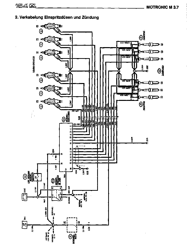
MOTRONIC M 3.7
The new
Motronicsystem M 3,7 equipped
with a controller of the newest technological development.
The
electronic ignition with „static distribution " was changed, with one coil
each for each spark plug (MONO COIL); in addition the achievement modules
are contained inside the steering box; this solution eliminates the
external ignition circle, and increases thus the reliability and the
security of the ignition system.
With this
version M 3,7 a phase injection (sequential) for each cylinder was realized. The injection moment is not
alike to no more for all cylinders, for each cylinder takes place
this at the optimal point of
injection, which is calculated by the steering box, depending upon
load, number of revolutions and
engine temperature.
REMARK:
The
moment planned in the calculation is the injection, from which the duration of injection is calculated. This
is the thermodynamic point and its correct control makes possible a still more exact
optimization of the engine run. The system activates also a correction of the duration of
injection. |
|||
|
|
|||
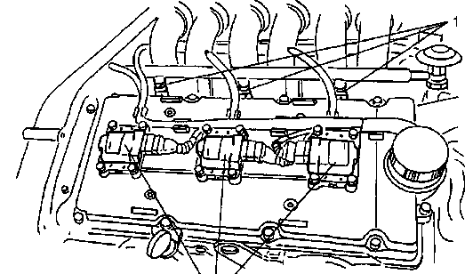 |
|||
|
|
|||
|
1. Electrical injection nozzle \|/
2. Mono coil 2 |
|||
|
|
|||
|
r |
|||
|
|
|||
|
|
||||
|
MOTRONIC M
3.7 |
||||
|
|
||||
|
With new
concept and Design „debit meter " (air mass measurer) is, with „warmed up
layer ". This new air mass measurer
does not contain as with the previous version „with flap " the sensor of
the sucked in air temperature; with this version this sensor is
separately attached before the debit
meter. |
||||
|
|
||||
|
1. Sensor air temperature
2. debit meters - air mass
measurers
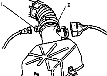 |
||||
|
|
||||
|
The
phase sensor was changed (sensor cam angle): It concerns no longer around
a sensor with magnetic induction,
but a sensor with hall effect. |
||||
|
|
||||
|
1. Sensor cam
angle |
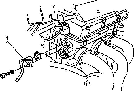 |
|||
|
|
||||
|
The number of revolutions and
reference mark sensor at the front wheel remain
unchanged. |
||||
|
|
||||
|
59 |
||||
|
|
||||
 |
 |
|||
|
|
||||
|
|
|||
|
|
MOTRONIC M 3.7 |
||
|
|
|||
|
The exhaust system consists of two separated systems (front
and rear Zylinderreihe)
with ever a catalyst and with ever an upstream Lambda probe
(1 and 2).
Before the two separate main catalysts is in each case a
Vorkatalysator (3).
The two same probes, send a
signal to the steering box over the remainder oxygen quantity in the
exhaust gas, everyone concerning the Zylinderreihe. The steering box
changes the mixing proportion for the appropriate
Zylinderreihe.
This solution makes a refinement
„for Lambda control possible ", which considers the differences between
the different cylinders, with from-following improving of the exhaust
gases and a reduction of the fuel consumption. |
|||
|
|
|||
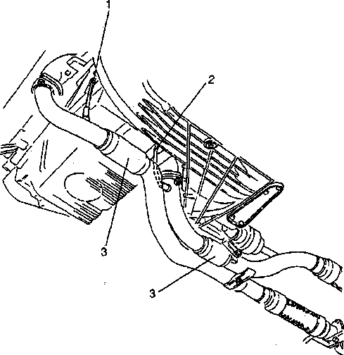 |
|||
|
|
|||
|
1. Lambda probe front Zyiinderreihe (cylinder
No. 4; 5; 6)
2.
Lambda probe rear Zylinderreihe
(cylinder No. 1; 2; 3)
3. Vorkatalysator |
|||
|
|
|||
|
60 |
|||
|
|
|||
|
|
|||
|
MOTRONIC M
3.7 |
|||
|
|
|||
|
Function „LDA " (idling
speed rise)
In
connection with the steering box ABS, activate the Motronic system the
so-called LDA logic, i.e. the waste
curve of the engine speed without load is made in the form of steps
(accelerotor pedal fast approved with
engine with high number of revolutions). |
|||
|
|
|||
|
Speed „v " |
|||
|
|
|||
|
A = brake beginning t = response
time
* with LDA ** without LDA |
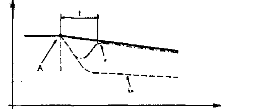 |
||
|
|
|||
|
Time „t " |
|||
|
|
|||
|
The information idling speed
becomes also to the controller of the Viscomatic
passed on and
evaluated. |
|||
|
|
|||
|
Control empty run
govern (signal PWM) |
|||
|
|
|||
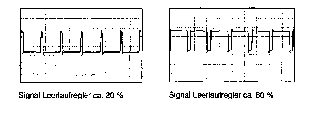 |
|||
|
|
|||
 |
|||
|
|
|||
|
|
||
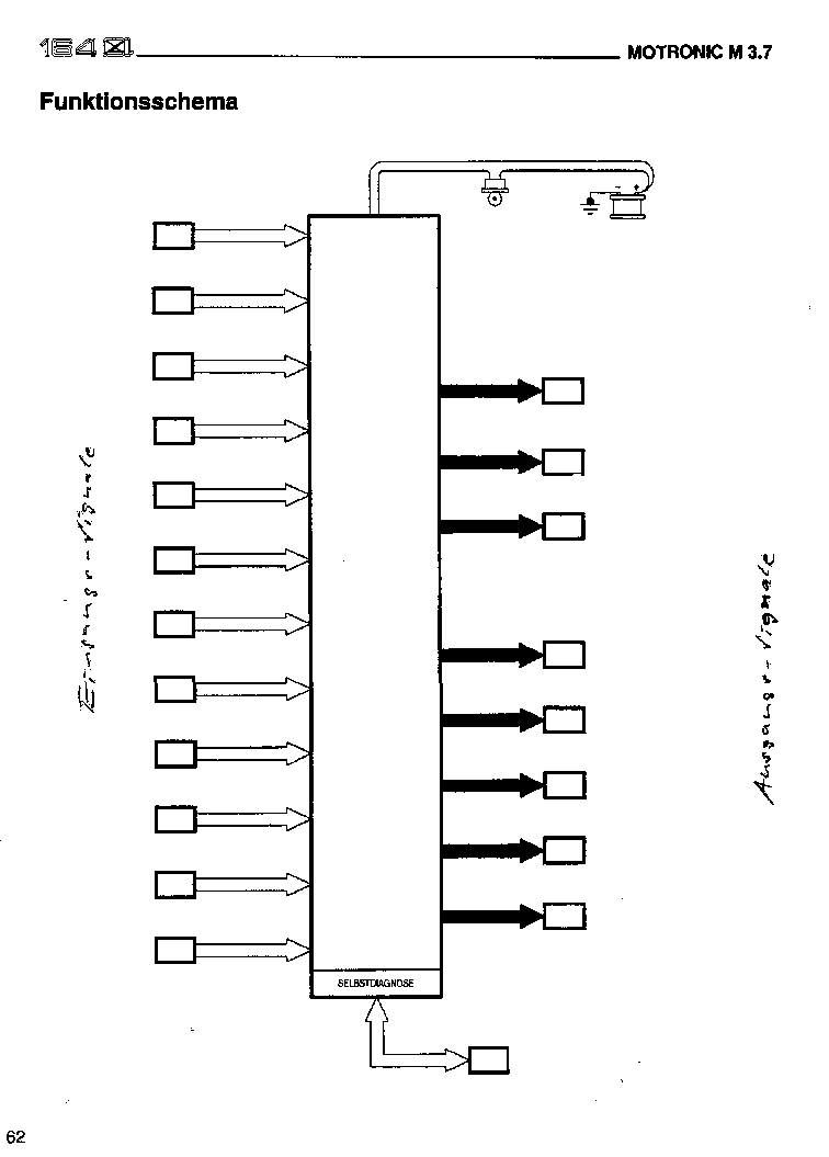
SENSOR MOTORENTEMR SENSOR TEMR SUCKED IN AIR AIR MASS
MEASURER FUEL
PUMP SENSOR BUTTERFLY VALVE MONO
IGNITION COILS (6 X) SENSOR
NUMBER OF REVOLUTIONS AND 8EZUGSMARKE ELECTRICAL INJECTION NOZZLES (6 X) MOTRONIC
STEERING BOX
INJECTION
AND IGNITION
M3.7 : SENSOR CAM
SHAFT LAMSDA-SONDE1UND2 ACTUATOR ATTITUDE
CONSTANT ONE MINOESTDREHZAHL (NO-LOAD
OPERATION) KNOCKING SENSORS 1 AND 2 ELECTRICAL
EVAPORATION VALVE (COAL ACTIVE CONTAINER) SPEEDOMETER SIGNAL
(OF ON-BOARD BOARD) ON-BOARD BOARD
(SIGNAL TACHOMETER) STEERING BOX ALARM
INSTALLATION LOADER
AIR CONDITIONING SYSTEM/CCOMPRESSOR STEERING BOX AIR
CONDITIONING STEERING
BOX V1SCOMATIC ABS STEERING BOX (LOA) PLUG
ALFA ROMEO TESTER |
||
|
|
||
|
|
||||||||||||||||||||||||||||||||||||||||||||||||||||||||||||||||||||||||
|
MOTRONIC M 3.7 |
iB£jM |
|||||||||||||||||||||||||||||||||||||||||||||||||||||||||||||||||||||||
|
|
||||||||||||||||||||||||||||||||||||||||||||||||||||||||||||||||||||||||
|
Operation diagramme injection and ignition
system |
||||||||||||||||||||||||||||||||||||||||||||||||||||||||||||||||||||||||
|
|
||||||||||||||||||||||||||||||||||||||||||||||||||||||||||||||||||||||||
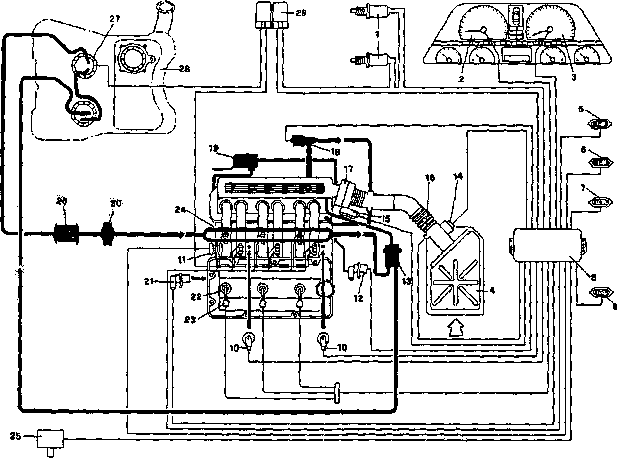 |
||||||||||||||||||||||||||||||||||||||||||||||||||||||||||||||||||||||||
|
|
||||||||||||||||||||||||||||||||||||||||||||||||||||||||||||||||||||||||
|
16. Temperature sensor sucked in
air
17. Butterfly valve
body
18. Actuator constant minimum number of
revolutions (no-load
operation)
19. Oil steaming
racer
20.
Pulsationsdämpfer
21. Cam shaft
sensor
22. Spark plugs
23. Ignition
coils
24. Electrical
injection nozzles
25. Electrical
evaporation valve (coal active container)
26. Fuel
filter
27. Electrical fuel
pump
28. Fuel
tank
29. Relay
group |
|||||||||||||||||||||||||||||||||||||||||||||||||||||||||||||||||||||||
|
63 |
||||||||||||||||||||||||||||||||||||||||||||||||||||||||||||||||||||||||
|
|
||||||||||||||||||||||||||||||||||||||||||||||||||||||||||||||||||||||||
 |
 |
|||||||||||||||||||||||||||||||||||||||||||||||||||||||||||||||||||||||
|
|
||||||||||||||||||||||||||||||||||||||||||||||||||||||||||||||||||||||||
|
|
|||||||||||||||||||||||||||||||||||||||||||||||||||||||||||||||||||||||||||||||||||||||||||||||||||||||||||||||||||||||||||||||||||||||||||||||||||||||||||||||||||||||||||
|
MOTRONIC M
3.7 |
|||||||||||||||||||||||||||||||||||||||||||||||||||||||||||||||||||||||||||||||||||||||||||||||||||||||||||||||||||||||||||||||||||||||||||||||||||||||||||||||||||||||||||
|
|
|||||||||||||||||||||||||||||||||||||||||||||||||||||||||||||||||||||||||||||||||||||||||||||||||||||||||||||||||||||||||||||||||||||||||||||||||||||||||||||||||||||||||||
|
Electronic steering box |
|||||||||||||||||||||||||||||||||||||||||||||||||||||||||||||||||||||||||||||||||||||||||||||||||||||||||||||||||||||||||||||||||||||||||||||||||||||||||||||||||||||||||||
|
|
|||||||||||||||||||||||||||||||||||||||||||||||||||||||||||||||||||||||||||||||||||||||||||||||||||||||||||||||||||||||||||||||||||||||||||||||||||||||||||||||||||||||||||
|
PIN-OUT STEERING
BOX
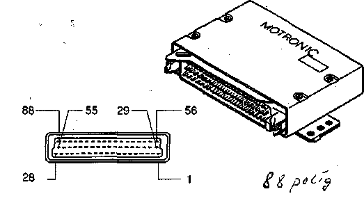 |
|||||||||||||||||||||||||||||||||||||||||||||||||||||||||||||||||||||||||||||||||||||||||||||||||||||||||||||||||||||||||||||||||||||||||||||||||||||||||||||||||||||||||||
|
|
|||||||||||||||||||||||||||||||||||||||||||||||||||||||||||||||||||||||||||||||||||||||||||||||||||||||||||||||||||||||||||||||||||||||||||||||||||||||||||||||||||||||||||
|
 |
||||||||||||||||||||||||||||||||||||||||||||||||||||||||||||||||||||||||||||||||||||||||||||||||||||||||||||||||||||||||||||||||||||||||||||||||||||||||||||||||||||||||||
|
|
|||
|
MOTRON1CM3.7. |
|||
|
|
|||
|
Components
The
electronic steering box receives the signals from the sensors,
which read, process the
function of the engine „" them after
one inside „the briefcases " stored logic, which connect among themselves optimally the
different parameters, and from-following the actuators activates, so that the engine
always functions with maximum achievement and
uniformity.
Here the
new and/or different components are
described in relation to the previous version M 1,7 |
|||
|
|
|||
|
Air mass measurer
(S5)
Operational principle air
mass measurement
The
heated surface is regulated on a constant temperature rise to sucked in
air. The moving by intake air cools and changes thereby the resistance of
the heated surface (PTC behavior).
The filament current is thereby the measure for sucked in air
mass. |
|||
|
|
|||
|
1. Plug
2. Measuring channel
3. Sensor with warmed up
layer |
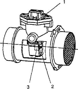 |
||
|
A = air
entrance |
|||
|
|
|||
|
The measured river is proportional to sucked in air
mass. |
|||
|
|
|||
|
REMARK:
The air
mass measurer determines directly air mass (and not the quantity as with
the previous versions with amount of air
measurer). |
|||
|
|
|||
|
|
|||||||||||||||||||
|
MOTRONIC M 3.7 |
|||||||||||||||||||
|
|
|||||||||||||||||||
|
Electrical
pin 1 - Measures pin 2 -
absolute dimensions pin 3 - supply 12 V pin 4-Meß-Signal
A = air
R-S = sensor with warm layer
River, which flows by R-S |
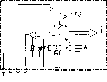 |
||||||||||||||||||
|
|
|||||||||||||||||||
|
12 3 4
RH = heating resistor
affects thermally R-S
R-S = sensor
resistance
G 1 = compensation
resistance
Blank = air temperature feeler
resistance |
||||||||||||||||||
|
|
|||||||||||||||||||
|
DATA CHARACTERISTICS SENSOR |
|||||||||||||||||||
|
|
|||||||||||||||||||
|
m = quantity (kg/h)
U = tension between pin 4 and 2 |
|||||||||||||||||||
|
|
|||||||||||||||||||
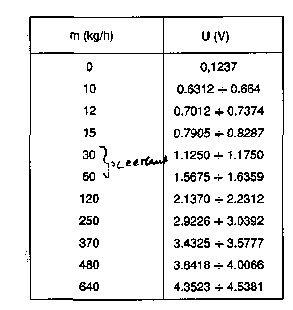 |
U [v]
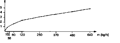 |
||||||||||||||||||
|
|
|||||||||||||||||||
|
NOTE:
The correct enterprise of the
air mass measurer depends on the condition of the air cleaner, which must
be examined therefore regularly. |
|||||||||||||||||||
|
|
|||||||||||||||||||
|
66 |
|||||||||||||||||||
|
|
|||||||||||||||||||
|
|
|||||
|
MOTRONIC M
3.7 |
|||||
|
|
|||||
|
Sensor cam shaft (S 52)
The phase sensor (sensor cam
shaft) consists of a device with hall effect. |
|||||
|
|
|||||
|
Electrical pattern |
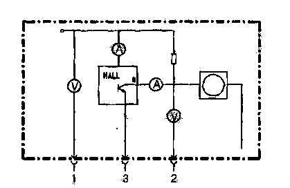 |
||||
|
Pin 1 =
supply pin 2 = exit signal
pin 3 = measures |
|||||
|
|
|||||
|
The
tension signal (as) forms, if the pin goes past from the cam shaft at the
sensor.
r v |
|||||
|
|
|||||
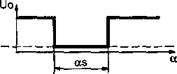 |
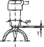 |
||||
|
Air gap T = 0.1 - 1.5
mm |
|||||
|
|
|||||
|
Lambda probe (S 35a and S
35b)
The two
Lambda probes are from the same design, as they are used also with the previous versions. |
|||||
|
|
|||||
|
Sensor air temperature (S 34)
The
sensor for the sucked in air temperature is separate with this version from the air
mass measurer. This concerns a NTC
sensor.
Electrical pattern |
|||||
|
|
|||||
 |
67 |
||||
|
|
|||||
|
•m
£Zfi&L>yfomw |
 |
||||
|
|
|||||
|
|
|||
|
A |
MOTRONIC M
3.7 |
||
|
|
|||
|
Mono ignition coil (A8)
Each
individual ignition coil on the cylinder heads, supplies directly a spark
plug without intermediate cables. The electrical pattern of the ignition
coil is shown in the illustration. |
|||
|
|
|||
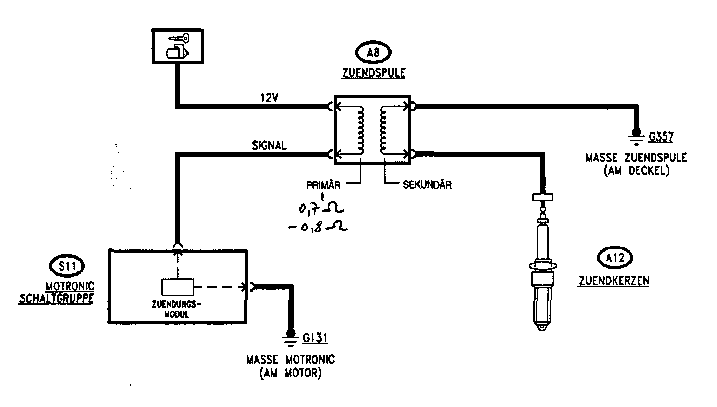 |
|||
|
|
|||
|
The
other components of the system do not differ from the before used Motronic M 1.7. |
|||
|
|
|||
|
|
|||
|
MOTRONIC M
3.7. |
|||
|
|
|||
|
Selbstdiagnose
The
steering box is equipped with a self diagnostic system and examines
continuously the signals of the
different sensors and compares it with the permitted limit
values: If these values are
exceeded, the system recognizes a disturbance and exchanges the abnormal values with average
values accordingly, so that a trip up to the next base of the
customer service net is ensured. This function is called „Limp home ".
In
addition the self diagnostic system makes a fast and effective putting
possible of the disturbances out under connection with Alfa Romeo the
tester (see appropriate publications).
The system does not plan the
examination by means of FLASHING CODES. |
|||
|
|
|||
|
69 |
|||
|
|
|||
 |
 |
||
|
|
|||
|
|
||
|
FUEL-SUPPLY
ÜNG |
||
|
|
||
|
Fuel system circle |
||
|
|
||
|
For the H'Ssö SJwird a closed
tank vent system with Kohieaktivbehälter used (fuel steams arrive to the engine into
the coal active container and over an electromagnetic valve are
supplied). |
||
|
|
||
|
1. Tank
2. Giver Kraftstoffstand
3. Giver Kraftstoffstand
4. Fuel separator
5. Connecting piece with tilting protection
valve and 3-Wege-Lüftungsventil
6. Pump with giver
Kraftstoffstand
7. Filter
8.
Coal active
container
9. Solenoid valve (steered from the steering
box Motronic)
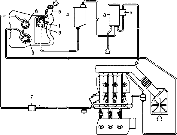 |
||
|
|
||
|
70 |
||
|
|
||
|
|
|||
|
FUEL SYSTEM |
, 11 |
||
|
|
|||
|
The
tank was again designed due to
the new rear axle and a larger capacity. |
|||
|
|
|||
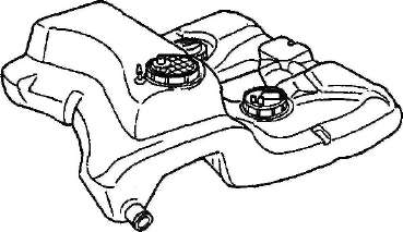 |
|||
|
|
|||
|
Due to
the special form of the tank a special solution became concerning the
arrangement of the pump and the
fuel condition giver (3) developed. In the upper range of the
tank is a giver with
float. |
|||
|
|
|||
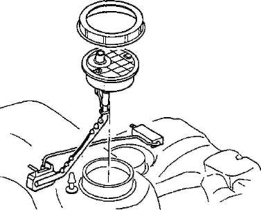 |
|||
|
|
|||
|
When
inserting the fuel condition giver (3 x) the installation direction must
be considered „arrows ". |
|||
|
|
|||
|
71 |
|||
|
|
|||
|
|
||||
|
FUEL SYSTEM |
||||
|
|
||||
|
The pump is in one of
the two lower ranges and leads the fuel over the filter to the injection
nozzles. This concerns an electrical immersed pump, like with the
previous versions. Together with the pump a further giver is
present. |
||||
|
|
||||
|
1. Pump
2. Giver |
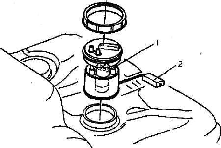 |
|||
|
|
||||
|
The moreover the return pipe
of the engine is, in it is together with the third giver a
device in the lower range, which passes the fuel on to the
pump.
This concerns a device,
which uses the suction effect due to the speed of the fuel
return and so the necessary energy supplies, in order to
promote the fuel from this part of the tank to the fuel
pump. |
||||
|
|
||||
|
1.
Giver
2. Device fuel
promotion
A: Return
of the engine B: to the pump
C: of the tank |
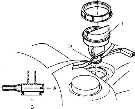 |
|||
|
B |
||||
|
|
||||
|
|
||||
|
FUEL
SYSTEM |
||||
|
|
||||
|
Electrical
pattern |
||||
|
|
||||
|
IO |
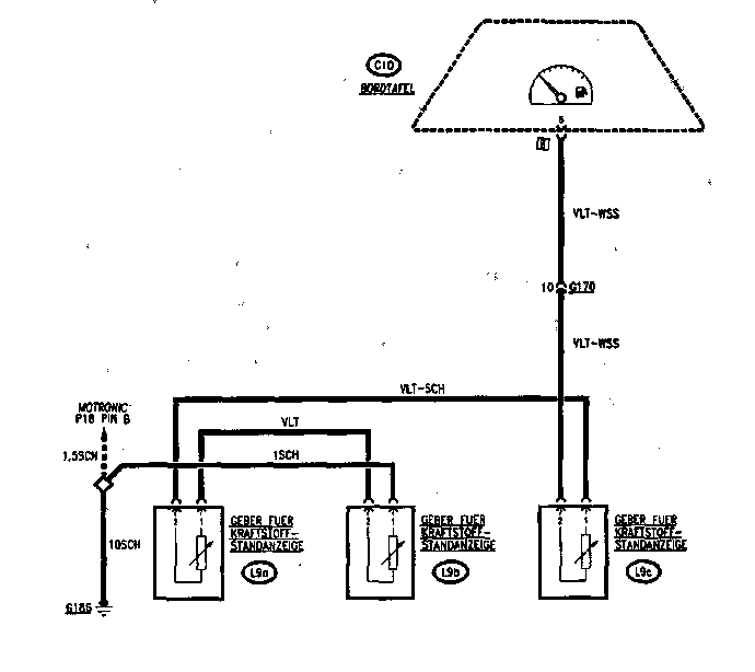 |
|||
|
I |
||||
|
|
||||
|
j-9aj) Giver (under rear
seat - left) Q-9tp
giver (under rear seat -
right) CL9cT)
giver trunk |
||||
|
|
||||
|
73 |
||||
|
|
||||
|
- M CZ&^iJwwne ** ' |
 |
|||
|
|
||||
|
|
||
|
1B^E_______________________________________________ ON-BOARD BOARD
On-board
board
Control light
VISCOMATIC® |
||
|
|
||
|
In the number of the control
lights is also the announcement „VISCOMATIC ". |
||
|
|
||
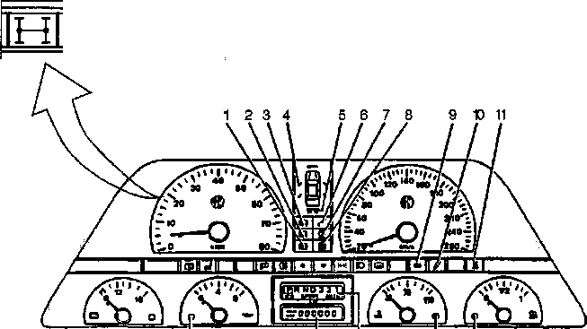 |
||
|
|
||
|
16
15 14
13
12 |
||
|
|
||
|
The
signal lamp shines when starting (approx. 2 seconds) and expires then; it
remains illuminating against it if
disturbances in the steering box arise VISCOMATIC. For further
details, see section „VISCOMATIC
". |
||
|
|
||
|
74 |
||
|
|
||
|
|
|||||||||||||||||||||||
|
ON-BOARD
BOARD |
|||||||||||||||||||||||
|
|
|||||||||||||||||||||||
|
Indicate fuel and signal
lamp to reserve
Also the
activation of the fuel condition indicator and the signal lamp reserve
is activated differently than so
far.
Only one
signal comes from the 3 givers (Televel) in the tank; this concerns 3
potentiometers, which are one behind
the other switched and so an entirely proportional signal stood according to the fuel in the tank
devoted.
This
signal is administered by an appropriate unit („interfaces absorption and
reserve "), which sends measures for
the lighting of the signal lamp reserve, if the appropriate ohm value indicates a very low
being located in the tank; in addition it sends the signal concerning the Kraftstoffstandes to the
instrument.
This unit
works with an internal delay of 15 seconds and „absorbs " so fast changes of the signals, which can
occur in the curve or while driving downhill. For this reason the signal lamp not falsely lights
up. |
|||||||||||||||||||||||
|
|
|||||||||||||||||||||||
|
Ohm value depending upon
announcements |
|
||||||||||||||||||||||
|
|
|||||||||||||||||||||||
|
approximately 9
liters |
|||||||||||||||||||||||
|
|
|||||||||||||||||||||||
|
|
||
|
ON-BOARD
BOARD |
||
|
|
||
|
On-board board: Interior pattern
REMARK:
Here only the specific part
for the version is indicated |
||
|
|
||
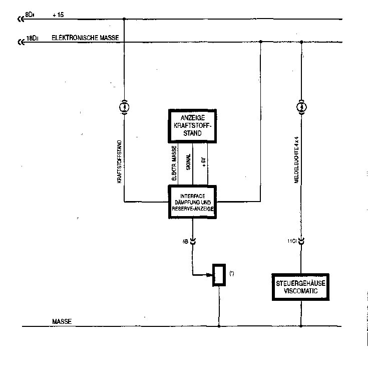 |
||
|
|
||
|
|
|||
|
Notes/notes |
|||
|
|
|||
|
77 |
|||
|
|
|||
 |
 |
||
|
|
|||
|
|
||
|
? |
||
|
|
||
|
. |
||
|
|
||
|
01.94/600/left |
||
|
|
||